Mastering the Art of Fine Detail
By Marek Barbaszynski

This is my Spitfire Mk. XVI in the markings of The Polish No. 308 (City of Cracow) Squadron. The 1/48 model has been built from the ICM kit with resin engine and a good deal of other additions and modifications.
The incentive to build this model came from the Polish newsgroup, pl.rec.modelarstwo. This lively community once started a so-called group project dedicated to various versions of the Spitfire, and I decided to catch on.
Introduction
For me this project was quite a challenge because it involved a whole collection of ”firsts”:
- First time I took part in a group project (unlike my daughter who participated in one already last year!)
- First 1/48th scale plastic build. I mostly build paper card models in 1/33rd scale.
- First kit from ICM (yes, that matters, and you will see why)
- First use of photoetched parts and resin components
- First time I used solely cyanoacrylate glue for construction
The general plan was to build a decorative model without taking too much care for historical accuracy. Yeah, right… that was before I purchased references for this project!

The sprues
When first examining the kit still in the hobby shop, the first impression was very good indeed – there was plentiful of delicate detail. As it often happens, the second look was substantially more critical and my enthusiasm decreased a bit. The ICM moulding had quite a number of problem areas – sink marks, several small pieces broken or incompletely moulded, plus flash abound everywhere. The color of plastic varied between sprues.
Everything was also generously smeared with mould release agent, requiring a thorough wash with a dishwasher detergent. This I did even before cutting off the parts to avoid getting grease all over my modelling desk!

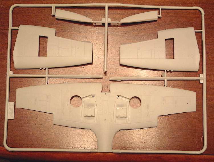
Kit photos, click to enlarge
On a side note, the ”sister” ICM Spitfire Mk. IX kit that is also in my possession looks much better. Maybe ICM has problems to get consistent results with quality of their kits, or maybe I was just unlucky with my sample.
At this point I decided to replace the smaller parts with photoetched ones. The Part set for Spitfire Mk. XVI came to the rescue, providing a lot of useful bits and pieces.
The assembly starts with…
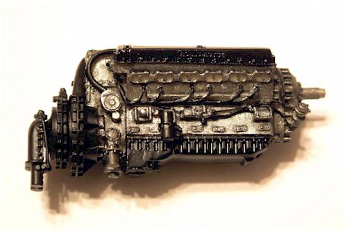
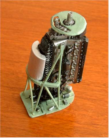
”Construction starts with the cockpit…” – wait, here is your chance to deviate from this mantra of aircraft modelling – I started with the engine. The Packard-Merlin from Aires makes a very good impression. It its delicately cast in resin and features exquisite detail including plumbing and cables.
It is already at this early stage that I fell into the reference loop. What is the correct paint colour for an US-built Merlin? About every reference picture in my posession showed something different. Finally I settled for a combination of steel and black paint, using Pactra acrylic black and Revell Steel enamel no. 91. I finished the paint job by applying a wash of ”dirt” using heavily thinned mixture of black and brown colours. A memory image of my car’s engine was used as a reference for the degree of weathering 🙂
In-progress photos, click to enlarge
Assembling the fuselage
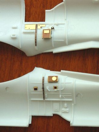
I added a few brass details in the cockpit – warning for another reference loop here! In the middle of it I received Modelmania No. 5 – Supermarine Spitfire IX-XVI from AJ-Press. This book contains loads of useful photos, mostly of preserved aircraft, in high-quality print. I immediately begun to regret the photoetched parts that were already in place, for they looked nowhere similar to the pictures. After some checking and comparing I realized that there were no two identical cockpits depicted anywhere, so small differences would not be so bad after all.
Besides cockpit interior I also added some styrene strips to imitate the internal structure of the fuselage in the radio and battery compartments so that it would be visible through the hatches I intended to model opened.
With my airbrush ready I could move on to some painting. It was not devoid of adventures. As advocated by many fellow modellers, I tried to apply a coat of primer first. For some reason (grease leftovers?) all I got was literally drowning one half of the fuselage in paint, while the other half remained nearly dry. Fortunately, the primer could be removed. Well, almost. A few ugly grey spots remained despite my best efforts to remove them.
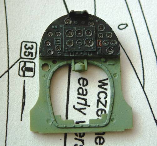
The instrument panel was painted matt black with subsequent dry brushing in light grey shade to highlight the instruments and switches. It was my first attempt at this technique and I considered the result very favourable.
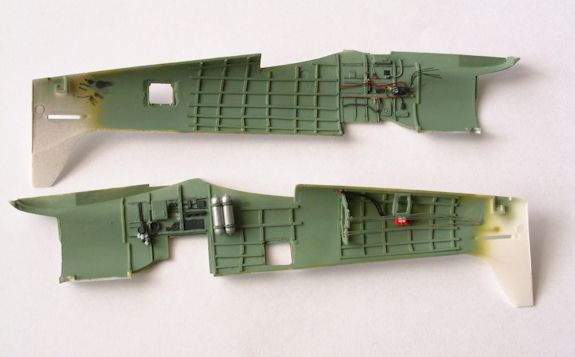
My painting blunders were not over yet. I painted the inner fuselage with Interior Green, only to find out in the daylight of the next morning that it was a wrong colour… Interior Green all right, but not RAF Interior Green! A repaint proved necessary, and it had to be done carefully as to avoid damaging the instrument panel already in place.
In-progress photos, click to enlarge
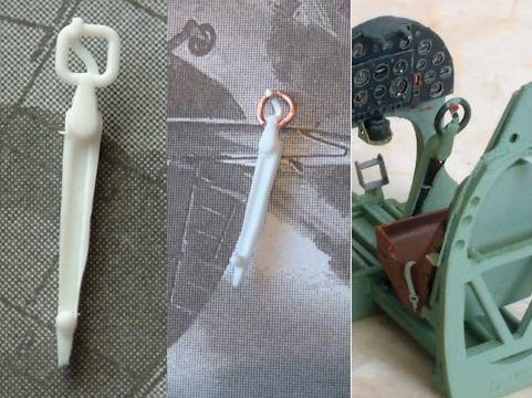
The attention now moved to the control column – for no apparent reason, ICM decided that the handle should have a square form instead of a classic RAF round grip. Replacement needed! I cut away the faulty part and made a new one from copper wire. But the pictures show that the control column had three electrical cables running along its length? A thin wire would do. A clasp for keeping cables in place? A strip of aluminium foil from candy packaging serves well for the purpose. And you can eat the candy, too!
Since I wanted to offset the ailerons on the model, I glued the control column a little off-centre. Then again, after a reference check I realized that control column in a Spitfire did not move sideways – only its top section did! As a result I re-adjusted the control column in the upright position and resigned from re-adjusting the ailerons.
With the completed seat, control column and instrument panel the cockpit still looked somewhat empty. I was not brave enough to sand off the details already moulded in the cockpit, although their size and placement did not correspond well to the references. I added more bits and pieces using paper, styrene sheet and various kinds of wire to replicate all those cables, levers, boxes and whatnots that exist in the real cockpit.
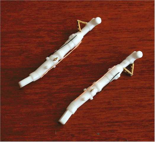
Oxygen supply tube was made from thin wire twisted around another wire. When finished, I was told that the same effect could be obtained using a piece of guitar string!
As I intended to leave the fuselage access hatches open, more detail was needed inside the rear fuselage. The battery, its cabling and the control wires were all scratchbuilt. Finding good reference images of this section was really hard – while there were plenty of pictures available, I could find only two that show the battery in place; all other showed an empty compartment.
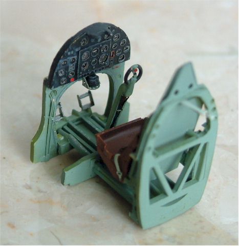
With all the photoetched parts on, the seat-floor-instrument panel assembly could no longer be inserted into the fuselage from below as shown in the instructions. I opted to glue the cockpit to one side of the fuselage, and then fit the other. In the absence of location pins, getting a good fit proved quite tricky.

The completed cockpit area
Wings and other things
Fuselage assembled, I added the wing. I enhanced the inner side of the center section with some plumbing and wiring that in theory could be seen through the ”floor” of the cockpit. At the same time I missed to add a piece of styrene ”skin” to imitate the curvature of the fuselage below the floor. Curiously, the presence of a huge empty space inside the wing is clearly visible through the cockpit, whereas all the wiring and plumbing is not!
The fit of wing components was quite bad, requiring a lot of filling and sanding. These are not my favourite pastimes and I admit that I am not too good at it. I experimented with various kinds of filler, with varying success.
My first filling on the model was done with general-purpose acrylic putty. Working previously on armour models, I used it with good effect. I especially liked the ability to wash the filler away with acrylic paint remover. Whenever such delicate finishing touch was enough, everything went well. But sanding was a different story altogether. The putty did not dry solid, but rather remained a little rubbery. When sanding, the putty would be dragged by sandpaper and torn from the gaps rather than stay in place as it was supposed to.
I subsequently was advised by someone to use a mixture of cyanoacrylate glue and talcum powder. It adhered very well, sanding was no problem, but it dried way too quickly.
After these misfortunes I decided to go back to Humbrol filler that I previously rejected for being too rubbery and fast drying. Compared to the other two alternatives it was simply great!
In the heat of sanding and filling I overdid a few bits. When attaching the windscreen, I carefully filled and sanded the joint line between the clear part and the fuselage. Later I realized (references in work again) that on the real Spitfire, the windscreen was grafted on the fuselage as a separate assembly with prominent joint line… So the windscreen was removed by force, together with the ah-so-carefully applied filler. Throw your references away while you can! The model, being already painted and given a protective coat of Sidolux (an equivalent of the Future floor polish – actually a good clear acrylic paint) looked rather odd…

The model painted and coated with acrylic floor wax.
Note the windscreen removed with brute force method – details explained in text.
To the paint shop
Just like the other stages of this project, the painting wasn’t free of adventures. I started with yellow leading-edge stripes on the wings. This I did by painting the appropriate areas in yellow and then covering the leading edge area with masking tape for all subsequent painting. Regrettably, through some inexplicable mistake, I made the stripes about twice as wide as they should be. The error was spotted only after all the painting was done and the masks removed – too late to start again, so no, I’m not going to correct it!
I painted my model with Pactra acrylics: A38 Grey and A116 RAF Dark Green on the upper side, A117 RAF Interior Green inside and A84 underneath.
For masking of the camouflage pattern I used pieces of newspaper cut to desired shape and smeared with masking fluid from Wamod. This technique may sound cheap, but it is working just fine. I find that ordinary masking tapes like Tamiya have a tendency to damage the underlying paint upon removal. This comment applies especially to Pactra acrylics, which do not adhere very well. Therefore I generally avoid using masking tape on painted surfaces.
At this stage the entire model was given a few coats of Sidolux floor wax. The effects of weathering were then applied with very thinly diluted Revell enamel no. 9 Anthracite. Exhaust and gun smoke stains were added with Pactra matt clear varnish mixed with a drop of black paint. The whole model was then finished with a single coat of clear matt Pactra.
During the painting stage I also worked to and fro with the undercarriage and the wing. The undercarriage struts were perhaps a bit too long, but I felt the difference was negligible so I left them as they were, with only minor brass and wire additions.
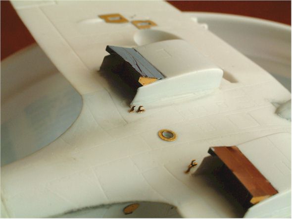
Brass parts were used also under the wing for cooler exhaust flaps and a few smaller details.
Then the wheels… the ones included in the kit had smooth tires with no tread. Replicating the tread would bring an obvious improvement, so I went about it. At first I tried to engrave the thread with a sharp needle, but the results were very uneven. On second attempt my wife agreed to give an extra hand. Each wheel was mounted on a toothpick and in the drill. With my wife holding the drill, the wheel was spun at small speed. With the same needle pressed lightly to the rotating tire, a quite satisfactory straight tread pattern could be produced.
In-progress photos, click to enlarge
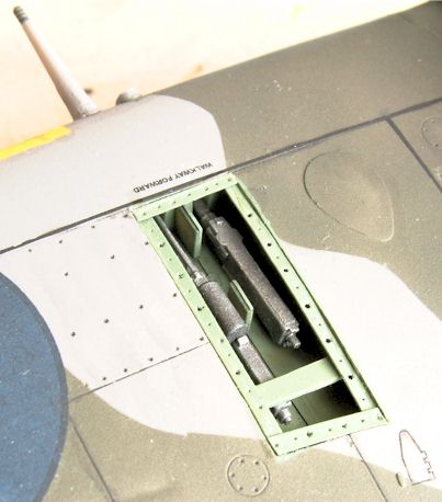
Detailing the Gun Bays
ICM has cleverly moulded the armament bay covers as separate items, thereby allowing to display the open cannon without any additional surgery. I boxed in the gun bays. The perforated sockets for the bolts that secure the gun bay covers in place were fabricated from strips of paper saturated with cyanoacrylate glue. These strips are really oversize, about twice as wide as they should be, but I could not make them any smaller. These would be beautiful if photoetched – I wonder why none of the brass vendors includes these items in their Spitfire sets?
The Decals
Frankly speaking, the decals of this kit were a nightmare, and stood for the most disappointing part of the project. They were extremely brittle and adhered poorly, causing some terrible silvering. I started with black walkway lines on the wing’s top surface, but the decals broke to pieces immediately after being removed from the water. I consequently painted the walkway lines with the airbrush.
A small curiosity is minor spelling error in stencilling on the decals: logation instead of location. This, however, is hardly noticeable.

ICM decals were most disappointing with huge silvering problems, as can be seen in this view.
Other decals were not just as bad, but they consistently refused to react to all decal solvents known to me. As is often the case, the satisfactory solution was devised only at the very end of decal application. The solution was to treat the surface to receive the decal with a liberal dose of acrylic paint remover (The one I use is from Wamod, Poland). This caused the underlying paint to dissolve, and I managed to press the decals into the softened paint coat with a soft brush. A final protective coat of Sidolux, then another of Pactra matt varnish and it was done. Unfortunately, even this risky technique did not work for decals applied earlier – their silvering remained very prominent. In the future, I’d rather keep safe distance from ICM decals.
The Engine Revisited
With the airframe ready and waiting it was time to turn back to the engine assembly. ICM has included the engine with the kit, but it was moulded undersized to fit under the thick plastic cowling. The Aires resin engine, on the other hand, is right on the money in size, but this quality makes it rather difficult to fit it to the model.
After some consideration, I opted to remove the moulded-in firewall and build a new one about a millimetre or so further aft so that the engine assembly would fit giving the correct overall length of the airplane. As a consequence, the lower cowling part had to be enlarged with a little filler.
The propeller backing plate provided with the kit was moulded too thick. When trying to sand it down I damaged the part beyond repair and had to make a paper replacement.

In-progress photos, click to enlarge
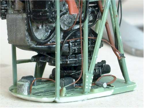
Studying the reference pictures showing the engine arrangement of various Spitfires, I noticed that the Aires engine was still missing a number of cables and ducts. I also learned that no two engine compartments looked identical. I added more wiring in places which seemed the most logical using various kinds of wire and styrene rod. The engine mount also needed enhancements: a few additional bars, some bolts and cowling attachment sockets.
The metal profiles with bolt sockets were made of paper soaked in cyanoacrylate glue. They came out somewhat crude – again, I wish somebody offered them in photoetched form! Bolt heads were made of stretched sprue cut into tiny slices. I found that the best way to handle these tiny parts was with a toothpick dipped in masking fluid.
Now the airframe was ready for fitting the completed engine. When in place, I noticed that some of the laboriously added pipes and cables were completely hidden from the view. I could have dispensed with making these… On the positive side, the whole thing looks rather impressive, so I can’t say that the work didn’t pay off!

The completed engine
At this stage the model looked quite complete, with only the doors and propeller remaining to be added. The latter was rather troublesome: I missed to sand the mould seams from propeller blades and now they ”reappeared” after some dry-brushing with silver. The seams were corrected, but the sanding damaged the ill-adhering Rotol logo decals on the blades, and I had to paint new ones with a brush.
Finally, attaching the undercarriage and cockpit doors was a piece of cake. Uff… Done.
Ready
Now that I look at my finished Spitfire, I have mixed feelings about it – this project really had its highs and lows to the fullest extent. On one hand, the model was a great challenge, it was fun throughout the entire construction and I learned a lot from it. On the other hand, I feel that the overall impression of the model is spoiled by those miserable decals and – admittedly – some faulty filling on my part.
I learned a lot about what is worth a detailing effort, and what isn’t. This knowledge will be carried on to the next project. I have also learned the hard way that it is always best to do things in the right order – so my planning needs to improve to avoid re-doing things.
Well there will be more attempts… see you then.


This article was originally published in IPMS Stockholm Magazine in November 2002.