by Martin Waligorski
Photo: Martin Waligorski
For the Spitfire fans, it may be hard to believe that the stubby Walrus was a creation of the same mind, and was produced during roughly the same period of time. R.J.Mitchell designed this flying boat in 1933 as an improvement to the already-in-production Supermarine Seagull, incorporating a pusher rather than tractor propeller, enclosed cockpit and a metal hull, allowing for a catapult launch from warships.
Popularly known as the Shagbat, the Walrus was first used by the Royal Navy for ship-to-shore communications, gunnery spotting, and maritime reconnaissance. But in 1941, when RAF began to form specialist air-sea rescue squadrons, the walrus became a mainstay of these. in total, seven squadrons in Britain and four in the Middle East flew the type. It is in this service that the Walrus gained the reputation for reliability and it’s ability to withstand considerable damage.
The Walrus would be, in my opinion, a very graceful modelling subject. The only mainstream kit that is known to me is an old Matchbox kit, produced to 1/72nd scale in the seventies. A quick look into the box and an opinion from my friend, Sten, make me believe that this was one of the better Matchbox offerings, but honestly, I can’t give you any details.
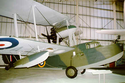
The aircraft featured here is presented at the Royal Air Force Museum in Hendon, London.
Supermarine Walrus Mk I
Looking at this picture, it’s really hard to believe that this is a Spitfire’s stablemate. Only two years differ the two aircraft in the service introduction, but these years translate to ages in aerodynamic design and aircraft technology…
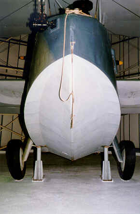 Looking at the aircraft’s hull from the front. A cross-section of the hull can be seen. The hull on this example is metal-skinned, implicating that this is a Walrus Mk I, produced by Supermarine. Later Walruses (or Walrii?) Mk. II were produced by Saunders-Roe and had wooden hulls.
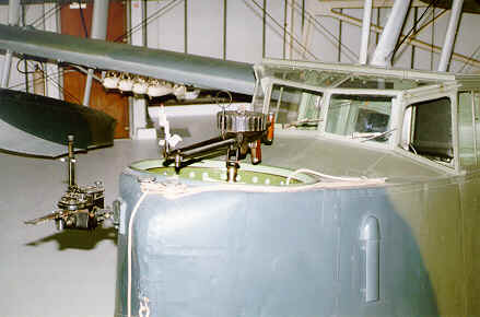
The detail of the bow. The gunner’s cockpit at the front was open, lacking even a simplest protection form the slipstream. The gunner was equipped with a single drum-fed Vickers K gun. The opening could be sealed with a round hatch, which is missing on this example.
The pilot’s cockpit, on the other hand, was fully enclosed and reportedly, quite comfortable.
The purpose of the black metal device on the left side of the photo is not known.
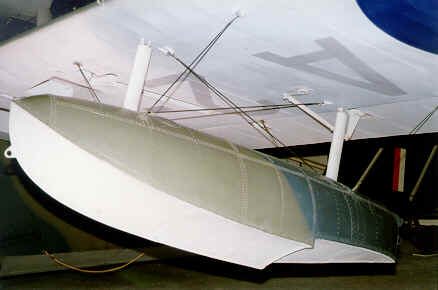
Stabilising floats were fixed to the lower wings. Note the rigging, and an anchor point at the float’s tip.
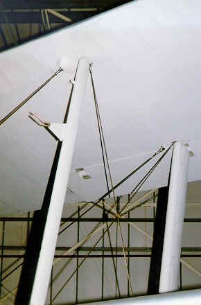
Even more rigging can be appreciated on this picture, showing main interplane struts on the port side.
The pitot tube is mounted on the front strut.
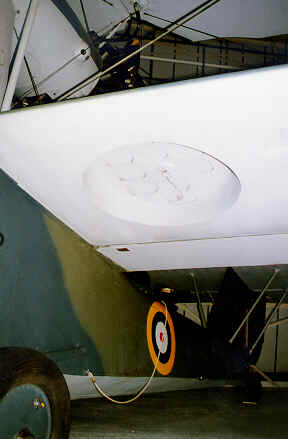 The main undercarriage was retractable in the simplest possible way, the main wheel folding away into this simple well in the lower wing. wheel legs were left out in the open even with wheels retracted.
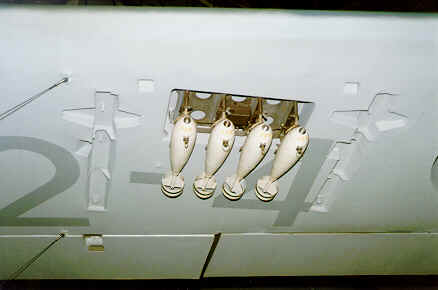
Another recess in the lower wing was intended to accommodate the aircraft’s offensive armament. Four tiny bombs shown here couldn’t possibly do much harm to the enemy ships, so it’s just as well that the Walrus wasn’t used in the attack role…
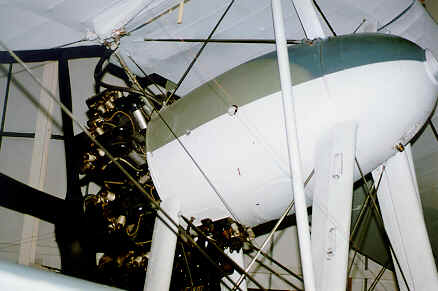
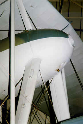 The interplane struts formed a distinctive X-profile with an engine nacelle in the middle. More rigging…
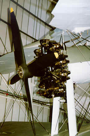
The overall view of engine installation. The engine is a Bristol Pegasus IIM2 620-hp radial.
The four-bladed propeller is actually mounted of two wooden two-bladers.
Still more rigging is can be seen on this picture…
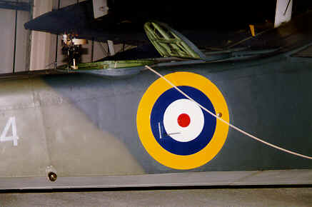
The rear part of the fuselage featured this gunner’s position. Like in the front, the gunner had a circular opening with a simple Lewis or Vickers K gun, the opening itself protected by the sliding hatch. The hatch in open position, as here, folded in two, thus forming a shield form the slipstream.
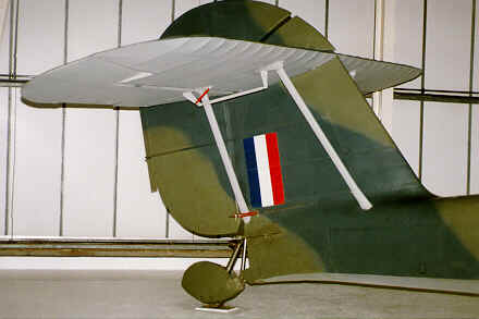
The flying boat’s tail consisted of metal covered vertical fin and fabric-covered horizontal stabiliser. All control surfaces were fabric-covered. The tail wheel was mounted inside a small float. Interconnected with the rudder, this could be used to direct the boat when on water.
This article was originally published in IPMS Stockholm Magazine in January 1998.
