by Sten Ekedahl
Many short-run aircraft models, for example MPM, Special Hobby, Azur, and multiple aftermarket sets contain propellers with separate blades. Such propellers can also be seen in mainstream injection-moulded kits from manufacturers like Hasegawa.
Although many of such kits will provide location pins and slots to ensure positive location of the blades in the hub, due to the small contact surface the assembly will invariably be prone for misalignment. Since each blade has to be positioned correctly in pitch, rotation plane and front view angle, there are many things that can go wrong without getting noticed at a first glance.
Although moulding the blades separately allows for more accuracy in cross-section, especially in the area closest to the hub, many modellers think that the entire approach is over-engineered and causes more trouble than its worth. Scott van Aken from Modeling Madness has often expressed his dislike for individual-blade propellers: ”It is vogue nowadays to have separate propeller blades. Frankly, I was quite happy with having all the blades attached to each other as I never had any alignment problems. Now I have to worry about blade alignment. This seems to be an area that is more complicated than it needs to be and I wish the manufacturers would revert.”
Multi-part propellers that come with short-run or resin kits have additional problems. These kits will often offer only a butt joint of propeller blades against a solid spinner, a solution not only flimsy, but small hell to align correctly. If the material is resin and you’re using cyanoacrylate glue, the result must also be perfect from the first time due to the extremely short curing time.
I faced just this problem in my recent conversion project, using Paragon resin conversion set for Spitfire Mk. XII. It prompted me to think about building a proper jig that would guarantee perfect alignment in all planes. I have made it, tried it, and it worked beyond expectations, so I will certainly use it every time from now on. I can also wholeheartedly recommend it to other aircraft modellers as the jig is simple and very effective.
Jig for a 4-bladed propeller
The following instructions use a 4-bladed propeller as an example. However, as you will see, the entire technique will work with any number of blades. At the end of this article I will describe how to modify the jig to other types of propellers.
Step 1
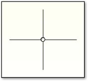
Cut a square piece from 1 mm plastic card, a bit larger than the diameter of the prop. Score two lines at 90° angles. The lines should be at least 30% longer than the prop blades.
Step 2
Drill a hole with the same diameter as the prop shaft in the centre where the lines cross.
Step 3
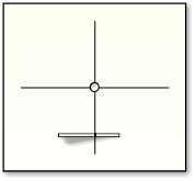
Cut a triangular wedge of ca 0.25 mm plastic card of about the above shape. Since the sloping side will set the blade pitch, adjust the angle to your liking.
Step 4
Put the spinner/prop hub into the hole and with a pair of dividers measure the height from the plastic card to the centre of the base for the prop blade. With the dividers find the spot on the wedge where the height is the same and mark it.
Step 5
Glue the wedge at right angles across one of the lines about 3/4 of the distance from the centre hole with the marking on the triangle slightly offset of the line (see next picture). This is to allow for half the thickness of the prop blade at this point. Note: Remember to check the direction of prop rotation!
Step 6
Hold one prop blade in position against the hub and at the same time resting on the wedge. Check that the centre of the blade is in line with the line on the card underneath it. Glue a small piece of plastic card to the wedge to act as a stop for the prop blade.
Assembling the propeller
Now your jig is finished! With the spinner and one blade in position in the jig, glue the blade to the hub. After drying, turn the prop 90 degrees and after aligning it, glue on the next blade with the aid of the jig. Repeat this for the remaining blades.
Other propellers
For a 3-blade prop, score the lines in step 1 at 120°, for a 5-blade prop at 72°, and for a 6-bladed prop at 60° angles.
This article was originally published in IPMS Stockholm Magazine in December 2003.


