by Martin Waligorski
Bf 109 Reprise…
When this webzine was started almost three years ago, I wrote: Could the IPMS Stockholm’s site do without a decent Bf 109 walkaround? Of course not…As our veteran readers will remember, we’ve been on this subject twice already: The NASM Bf-109G-6 was our walkaround subject in April 1997, and Bf-109E from Hendon’s RAF Museum in July of the same year. Especially the G-6 feature is of special meaning to me. These six not-so-perfect shots taken by me on a visit to Washington museum were a start to our today quite satisfying (and still growing) collection of aircraft walkarounds.
These two essays by no means provided a complete coverage  of the vast subject which the Messerchmitt’s classic fighter provides. So I’m not afraid of repeating myself now by showing another Gustav, this time a G-10. Another factor making just a G-10 interesting is the recent interest in the final Messerschmitt variants shown by mainstream kit manufacturers like Revell/ProModeler or Hasegawa.
Our subject this month, the Bf 109G-10 werk nummer 611943, has been built at the Wiener Neustadt factory in 1944. It saw service with II./JG52 on the Eastern Front, but was surrendered to the American forces at Neubiberg Airfield near Munich at the end of hostilities. Brought back to the USA for evaluation, this machine was saved from scrapping by Planes of Fame Air Museum founder, Ed Maloney, in 1957.
It is currently on display at Grand Canyon division of the Planes of Fame where these photos were taken.
Messerschmitt Bf 109G-10 in Detail
Since there are many photographs, the material has been divided into sections presented below.
General views and Fuselage
Bf-109G-10 on display in Grand Canyon Planes of Fame Museum, Valle, Arizona.
The aircraft wears a carefully restored camouflage which is supposed to represent the one carried by 611943 in service with II./JG52. Even the original stencils have been carefully re-applied.
The camouflage is RLM 76 lower surfaces with RLM 02 + RLM 82 upper camouflage and fuselage mottle. The use of RLM 02 in upper camouflage is definitely non-standard for the end-war period, but knowing the variation of late war Luftwaffe paint schemes it’s use cannot be excluded. Photo: Martin Waligorski
A distinctive feature of the G-10 was this modified cowling housing the then-newest Daimler Benz DB 605D engine. It differed from earlier Gustavs by large streamlined bulges on both sides of the rear engine cover. Two types of the covers were used on G-10, and the one shown here is type 100, recognisable by the blister in front of exhaust stacks, covering the oil lines. The same cover was used in Bf-109 K-4 production.
What cannot be seen on a single photograph is that the bulges on the port and starboard sides were asymmetrical. The port bulge, shown here, was significantly deeper and longer as it had to house the enlarged supercharger of a DB 605D.
Note also the loose fit of the engine cover at the firewall joint, and a long raised blister on the upper wing surface. More about it later. Photo: Martin Waligorski
A look at the starboard engine cover shows that the bulge at this side is less pronounced. On this side it’s function was limited to cover a spent cartridge chute for the fuselage gun (it’s opening is visible at the top).
Other interesting details are the welded exhaust stacks and a starter crank, a common feature all Bf 109 versions.
Photo: Martin Waligorski
A closer look at the two other distinctive 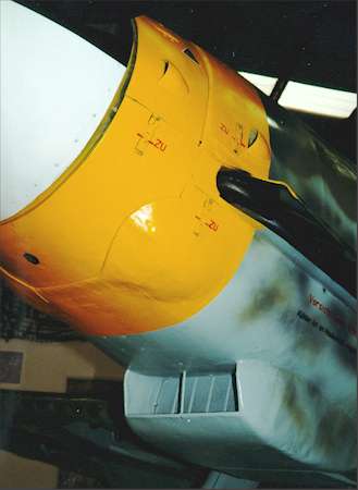 features of G-10. The previously named two blisters in the lower front cowling and a much deeper oil cooler. Again, both are peculiar to the type 100 engine cover. The alternative type 110 had no blisters and more shallow, but wider, cooler fairing.
The vertical bar in the middle of the cooler’s intake is actually a drain pipe, designed to lead away oil running down from propeller gear thus preventing it from clogging the cooler mesh.
Photo: Martin Waligorski
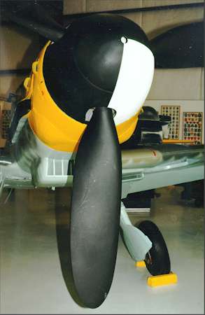 More power delivered by the DB 605D prompted a propeller upgrade to this type with paddle-like blades.
Although the museum specifies this aircraft as Bf 109G-10/U-4, I have my doubts. Designation U-4 meant a factory-mounted MK 108 30 mm cannon firing through the propeller hub. It would simply require much larger opening in the spinner than the one shown here.
After writing the above words, Larry Samhat pointed out to me that the propeller and spinner assemblies are not original. Other reference photos of this G-10 show the cockpit cannon breach cover to be the larger version that was fitted for the larger weapon. Probably all of the G-10’s brought to the U.S. after the war were 30mm armed models.
Photo: Martin Waligorski
Another view of the lower cowling and the supercharger air intake. The stencil below exhaust stacks reads: Vorsicht beim Öffnen. Kühler ist im Haubenteil eingebaut, which means: ”Careful when opening. The cooler is built into the cover.”
Another interesting difference between the port and starboard sides of the engine is an extra cover over the exhaust stacks. It’s function was to prevent the exhaust gases of being ingested into the supercharger. Photo: Martin Waligorski
Some older sources call this upgraded clear-view cockpit canopy for Galland Hood, but the correct name now agreed upon is the Erla Haube. The heavy armoured glass head protection was mounted directly to the canopy, which made opening and closing it a tough job for the pilot, especially in the bail-out situation.
Barely visible is what appears to be a complete instrument panel, but the Revi reflector gunsight is missing.
Photo: Martin Waligorski
Rear fuselage section didn’t change much throughout the 109’s lifetime, only the different hatches and caps were moved around accordingly the equipment placement inside the fuselage. Stencils visible from left to right denote: pressurised air flasks for machine gun operation (on top of the cross); MW50 water-methanol tank (above the ”13”); electric socket (in front of the ”3”) and Sauerstoff für Atemgerät (ditto, blue ring).
Another features often seen on late-war Messerschmitts are the lack of antenna mast and a direction finder loop placed behind the cockpit. Photo: Martin Waligorski
Still further aft down the fuselage’s starboard side. Of note is how the fuselage sections are smoothly flush-riveted together. Panel lines are barely visible! Photo: Martin Waligorski
Tail
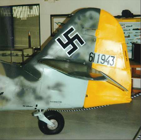
Tail configuration is another area where G-10s often differed between various production batches.
This one has an upsized tail wheel of the type similar to one used on Fw 190. Nevertheless it is mounted on the short leg making the aircraft ”sit” similarly to earlier Gustavs.
The vertical tail has been enlarged as compared to G-6 and earlier variants, but even this component could vary in shape. This one is of metal construction with a sharp ”heel” of the rudder and a single trim tab. Photo: Martin Waligorski
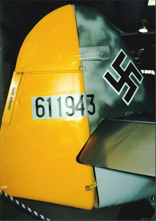 A look on the opposite side of the rudder reveals it’s mass balance and a long trim tab actuator.
The werknr. 611943 conforms to the one originally assigned to this aircraft in the factory.
Photo: Martin Waligorski
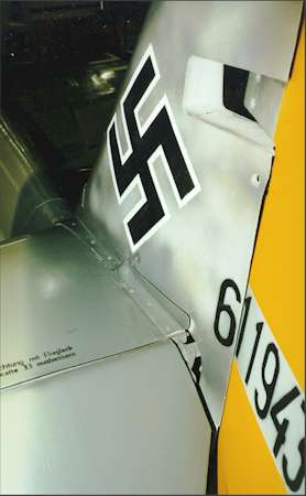 …and yet another view of the tail, this time a close-up of the joint between horizontal and vertical surfaces.
Photo: Martin Waligorski
Wings and main undercarriage
Despite the seemingly identical configuration, the undercarriage of the G-10 and K-4 was miles away from that of the earlier variants. Some of the changes are visible here: undercarriage track was considerably widened, resulting in the prominent ”gaps” between the leg and the inner end of the wheel well. Legs had been made thicker, and the wheel covers split into two-part assemblies.
The rectangular openings between the wheels are spent cartridge ejection chutes for the fuselage-mounted guns.
This aircraft lacks the centerline drop tank rack, but the four hardpoint hooks and a fuel line for it can be seen further aft.
Photo: Martin Waligorski
Another feature of the new main undercarriage was a new wheel of 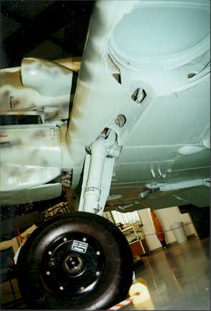 the 660×190 mm format, as opposed to 660×160 mm of the earlier type.
The photo also offers a good view of the wheel well interior, notably devoid of wiring and plumbing often seen on other aircraft of the period.
Photo: Martin Waligorski
The view of the upper wing surface with the lowered flaps in the foreground.
The blister outside of the walk area extends from the leading edge over almost the entire wing chord. This blister provided more room for the enlarged wheels of the new undercarriage.
Note also the wing root fairing. Photo: Martin Waligorski
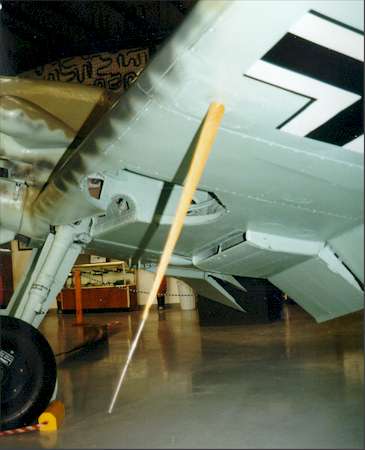 An interesting object under the port wing is the Morane antenna mast. The color is…natural wood. This is correct: RLM specs called for these, and other wooden antenna masts, to be painted with clear varnish only.
Photo: Martin Waligorski
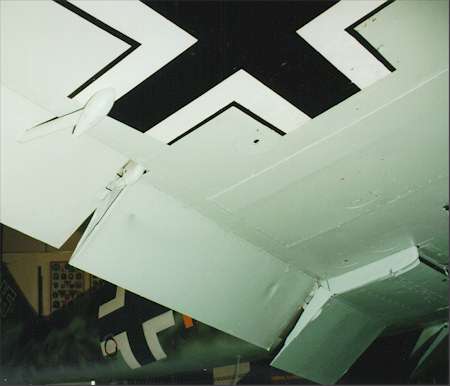 The last view of this photo essay is of the wing’s lower surface. Nearest the camera is the aileron mass balance, followed by an aileron hinge, a lowered landing flap, and an underwing cooler.
Photo: Martin Waligorski
This article was originally published in IPMS Stockholm Magazine in October 1999.


