Detailing Heller’s 1/400 Gneisenau
by Ulf Lundberg
English translation by Martin Waligorski
| Note for Swedish readers |
| Den här artikeln finns även tillgänglig på svenska i form av ett PDF-fil, 435 KB |
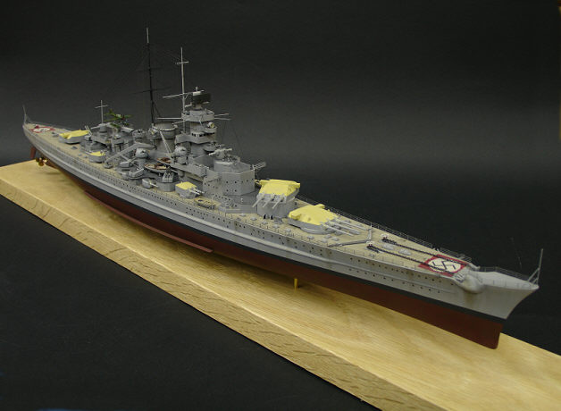
Heller’s 1/400 Gneisenau built, detailed and finished by the author
About the Ship
The Treaty of Versailles drastically limited the size of Kriegsmarine’s warships to 10 000 tons or less, roughly the size of a heavy cruiser in most navies. Presented with a problem, the German engineers developed a novel solution of pocket battleships, designed as commerce raiders faster than any ship more powerful than they and more powerful than any ship faster.
The viability of the concept was threatened by the fact that the old Royal Navy battle cruisers and the entirely new French Dunkerque and Strasbourg were both faster and more heavily armed than the German ”pocket” vessels. Clearly, more tonnage was required, and with a new Nazi government in power, it was decided to push the arms treaty limitations aside and proceed with two new and much larger battle cruisers. These ships became Scharnhorst and Gneisenau, and like all other major ships of the Kriegsmarine, they were intended to operate as commerce raiders rather than main line units.
The Gneisenau was laid down in Kiel on 6 May 1935 and launched on 8 December 1936. On 21 May 1938 she was commissioned for the service with the Kriegsmarine. After a few operational trial and training missions she was docked again in January 1939 for rebuild. It was then she received her characteristic handsome silhouette which made her look as fast as she was – the gracefully elevated ”Atlantic” bow and the slanting stack.
With the outbreak of the Second World War, Gneisenau and Scharnhorst were the largest ships of the German navy – the Bismarck and the Tirpitz were not commissioned until a few years later. Both ships were involved in several raids against British shipping. On 23 November 1939 they sank the British Armed Merchant Cruiser HMS Rawalpindi.
On 8 April 1940, the battle cruisers had a short and inconclusive clash with HMS Renown during which the Gneisenau received three hits, damaging her aft turret and radar and forcing her back for a quick repair in Kiel. Success came on the next mission, on 8 June, when German ships discovered and sank the aircraft carrier HMS Glorious and her two escorts, the destroyers HMS Acasta and HMS Ardent.
Between January and March 1941, Scharnhorst and Gneisenau made their most famous commerce raid, Operation Berlin. 22 merchant ships were sunk and the Germans were able to escape pursuit despite the large effort on the part of the Royal Navy. At the end of the operation the two ships laid in the French naval base at Brest. It was thought that this would brought them conveniently close to the Atlantic for the next sortie, but the British managed to keep them at bay through persistent bombing. After a full year in harbour, Brest was deemed too unsafe for the Germans, and the ships, together with heavy cruiser Prinz Eugen, returned to Kiel in the daring and famous Channel Dash under the nose of the British. Even today, this operation is quoted in military schools as an example of effective coordination between fleet and air force.
The Channel raid cemented the ships’ reputation in the British press as ”The elusive sisters”. The Germans did not escape unscathed, though: both battle cruisers run into mines and had to be repaired at dry dock in Kiel. There, on 27 February 1942, Gneisenau was hit by a bomb which penetrated the bow into the forward ammunition magazine, causing further explosions which effectively demolished the entire bow area.
After this event, Gneisenau was moved to Gotenhafen in the Baltic outside the range of RAF bombers, but the writing was already on the wall. On Hitler’s expressed orders the reparation work was stopped during 1943. Gneisenau remained non-operational in Gotenhafen harbour until 1945. On 27 March 1945, with Soviet onslaught in East Prussia and the siege of Danzig, Gneisenau was scuttled in the entrance to the Gotenhafen harbour
| Gneisenau data sheet |
|
About the Model
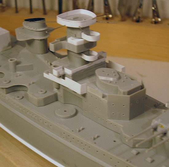
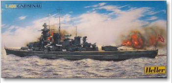 The kit used for this model was an old Heller offering dating back to the 1970s. The quality of the moulds was in par with the kit’s age – in other words, nothing to get overly excited about. On the positive side, the shapes are usually correct but the details were rather soft. Therefore I have chosen to enhance the model with quite a lot of own-manufactured details and a photoetched set from Tom’s Modelworks.
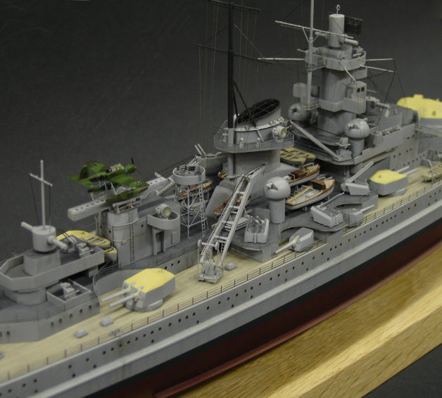
Assembling the Heller’s kit right out of the box would result in something of a compromise between Gneisenau’s looks at the different stages of her operational use. Because I wanted to represent the ship as she looked in 1941 at the time of Operation Berlin, I had to supplement it with a new seaplane hanger and catapult and a 20 mm Flakvierling tower aft of the stack.
I think that an essential quality of a good ship model is balancing the level of detail throughout. Just adding a set or two of photoetched parts could result in placing the intricate metal parts next to clumsy lumps of plastic such as those representing AA guns or lifeboats in Heller’s Gneisenau. In such situation it is better to rebuild a few parts from scratch in order to enhance rather than oppose the advantage of using photoetched details in the first place. A skilful Internet dweller would no doubt locate a resin or white metal set for those AA guns, but I’m no such person. On the positive side, I find scratchbuilding small detail quite entertaining.
Following is the detailed description of my detailing work on the Heller’s kit.
The Hull and Superstructure
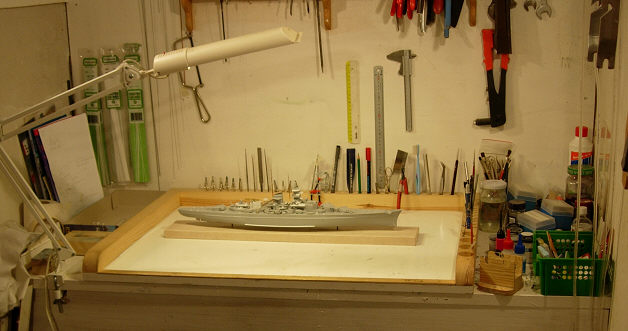
The project started with assembling the hull. I have reinforced the hull internally along the keel line to be able to securely attach the model to the base using when ready. There was a number of sink marks which had to be filled in. Also, I wasn’t entirely happy with the shape of the bow, so the area was filled internally with Milliput and the bow sanded down and shaped to a more pointed appearance. In the process, the entire hull was also sanded smooth.
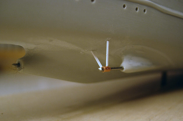
Detailing work started by drilling all the portholes and vents in the hull and superstructure. Then the propellers were detailed with new axles made from piano wire.
I used thin plasticard extensively to add features like bulwarks and supports to the ship’s bridge and superstructure.
Adding the 20mm Flakvierling
The quadruple AA gun position aft of the stack was placed on an elevated platform. Building the platform and its supporting structure was a new challenge to me. The main difficulty was assuring that the assembly was symmetrical and properly aligned, so I created a jig which supported the beams during construction.
The jig consisted of a piece of particle board with a hole which was drilled exactly vertical using a power drill an a stand. The hole acted as a holder for the length of thick piano wire, which in turn formed a steady central support for the entire structure.
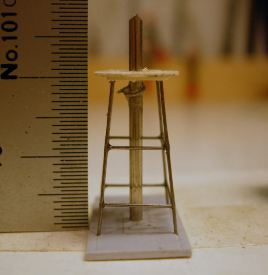
Then a square was traced on a piece of plastic sheet with dimensions corresponding with the width of the structure at the base. A small hole was drilled in each corner of the square, and another one for the central piano wire in its middle point. Then the square was threaded on the wire, providing anchor points for the four upright beams.
The next step was building the circular platform for the gun. This was duly assembled from two layers of 0,5 mm plastic sheet. In the lower layer I drilled the holes to accept the four upper ends of the supports and again, a hole for the central piano wire was provided in the middle.
Now the platform was threaded on the centre wire, and the top ends of the four upright beams placed in their sockets on the platform’s lower side. I double-checked everything for adjustment and then superglued the assembly together.
Now was the time to add the girders. To assure horizontal placement, the jig was extended with a square of plastic sheet laid horizontally at the proper height. Now the lengths of wire forming the girders had to be cut to exact length for precise fit. I achieved this by cutting them a trifle too long and then gradually sanding down and frequently dry-fitting for correct length. Once precise fit was achieved, the rest was a simple mater of supergluing the girders in place one at a time.
Now the only remaining elements of the trusswork were the diagonal beams. My approach was to made them from lengths of stretched sprue. In retrospect, I’d rather use nylon fishing line instead, which would have been stronger and better-looking.
The completed structure was left aside in the jig for another day or so to ensure that the glue has cured completely. Then came the moment of truth: would the trusswork withstand the stress of removing it from the jig? It did!
The reader may wonder now it the assembly was symmetrical as intended. The answer is yes, or at least – sufficiently.
On my part I hope that the above description of the process is understandable in case the reader would like to do a similar exercise himself.
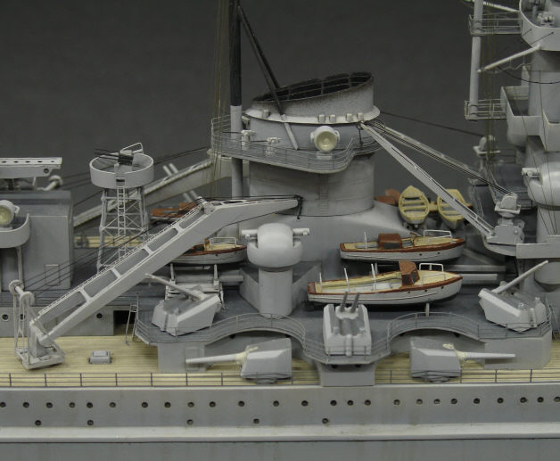
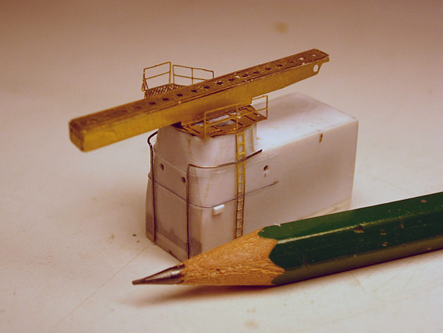
The Flakvierling tower in place among other added detail in the ship’s centre section.
Other Bits
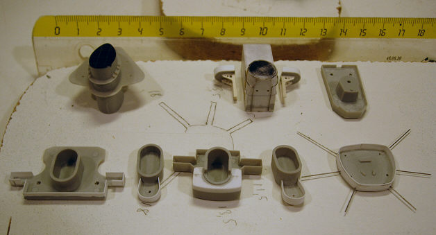
The Flakvierling itself and the other anti-aircraft guns were build from miscellaneous plastic bits, with barrels produced from 0,2mm guitar string (the thinnest e-string). Building the guns was easy compared with the structure described previously.
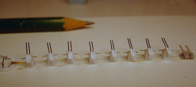
Eight twin 37mm AA guns made from plastic strip and piano wire. Compare with corresponding kit part to the extreme right.
One detail which I frequently rework on my ship models are the ship boats and launches carried onboard. The reason for this becomes obvious if you look at the next picture – the kit parts are usually grossly oversimplified, with overly thick thwarts and often also ejector pin marks marring the inside of the hull. I cut away the moulded thwarts and added floorboards and thwarts made from plastic strip. I also thinned down the gunwales.
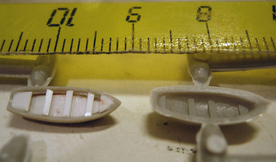
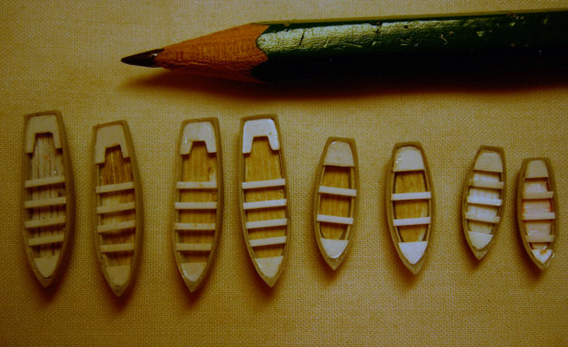
Detailed lifeboats make a world of difference to the model’s final appearance. Of course, you must be prepared to do some ”series production”.
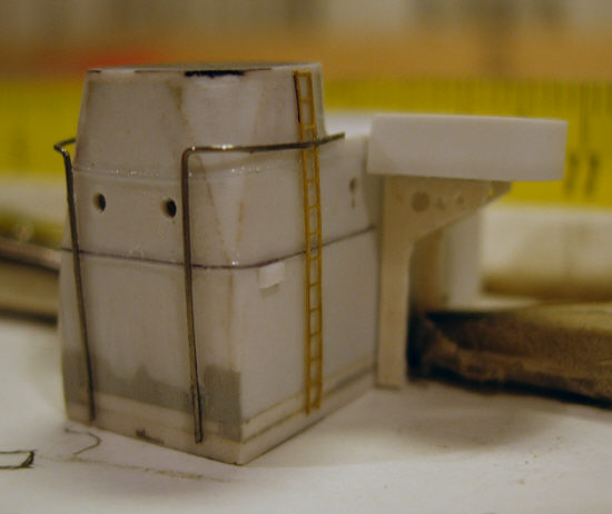
The seaplane hangar was scratchbuilt from plastic card and enhanced with brass ladders and other details. The catapult itself is a beautiful piece provided in the Tom’s Modelworks set.
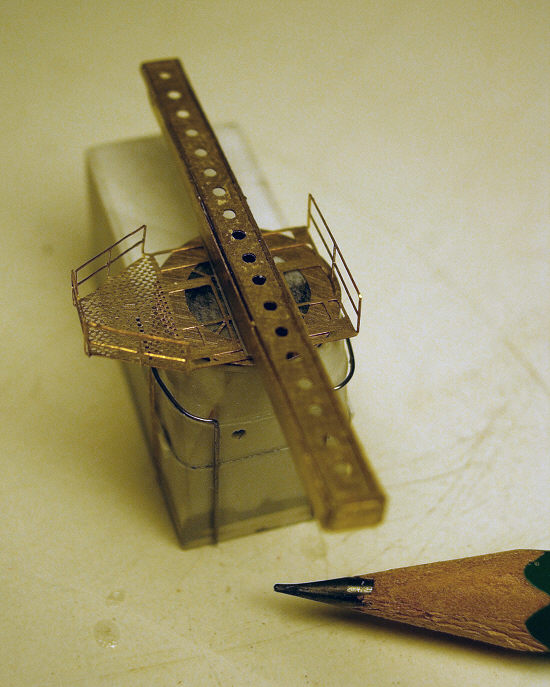

The moulded masts and yards in the kit were replaced entirely with scratchbuilt ones made from brass tubing, piano wire and photoetched footropes and railings. The extra rigidity given by use of metal for these structures proved to be of great benefit when rigging the model later.
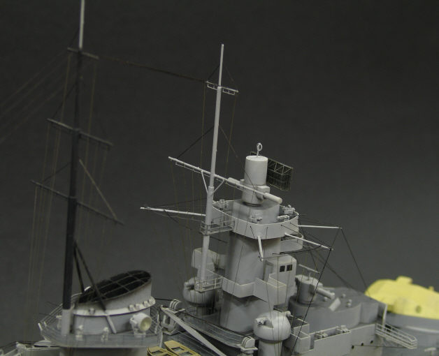
Scratchbuilt masts installed, painted and rigged
A fair share of other detail was also added to the model, but rather than going into further construction details, I’d rather stop here hoping that the reader would bear with me to the next part – the painting.
![]() Continue to part 2: Painting
Continue to part 2: Painting
This article was originally published in IPMS stockholm Magazine in June 2006