by Martin Waligorski
The elegant Fairey Battle presented an approach to the bomber design which was attempted several times during the pre-war period. The idea was to produce a bomber which could exceed it’s contemporary fighters in speed and performance. When Battle first flew in 1935, it was certainly much better than the then best of RAF fighters, the Hawker Fury. The new bomber promised to emulate the outstanding success of it’s German counterpart, the excellent Heinkel He 70.
However, within only the following year, several new fighter prototypes (Messerschmitt Bf109; Heinkel He 112; Hawker Hurricane; Supermarine Spitfire) where constructed and flown both in Germany and the U.K. which broke the speed supremacy of these sleek single-engined bombers.The Germans learned the lesson quickly and moved on to other bomber designs. The British failed to take the lesson, and continued the production of what has already been an obsolescent, too slow and underarmed combat aircraft.
In consequence, when the war in the West broke out, the Battle had been hopelessly outclassed by German fighters. The losses during French campaign were so terrifying that the remaining Battles were hastily relegated to night operations and then to training and target-towing duties.
Life has not been easy for those modellers who want to add a Battle to their model collections. As far as I know, there has been only one kit, issued some years ago by Airfix in 1/72nd scale. Reasonably good as a kit, it has a major problem – it represents a shape of a prototype, which was markedly different from the production machines. It just happened by accident, as the Airfix toolmakers simply obtained a wrong set of drawings from Faireys. When the mistake was discovered, it was already too late, and this only Battle kit was issued with the built-in fault.
It is not easy to see a preserved Battle. RAF Hendon museum has one, recovered from a crash site on Iceland and beautifully restored.
Fairey Battle Mk I

General view of the Fairey Battle in RAF Museum’s Bomber Hall.

Looking closer at the aircraft’s nose. The Merlin engine is enclosed in a streamlined cowling. The combined carburettor intake and cooler were placed below and to the rear of the engine.

The Battle lacked propeller spinner, leaving the variable pitch mechanism exposed.

The glasshouse-style canopy covered the roomy crew compartment for three. This is pilot’s cockpit with the hood partly slid back. The ring-and-bead type sight was used by the pilot to aim the only forward armament of the Battle, a single 0.303″ fixed machine gun.

The rear part of the ”glasshouse” was hinged, allowing the rear gunner to operate an equally unimpressive rear armament visible here – a single, drum-fed Vickers K gun.
Note how the antenna mast goes right through the canopy glazing. Other interesting feature is the continuous fuselage decking between the gunners’ and pilot’s compartments. The third crew member (navigator/bombardier) had his office inside the fuselage.

The rear fuselage. An absolutely smooth fairing joins the wing with the fuselage. Other feature of note is the cut-out in the upper fuselage decking, used to stow the gun’s barrel.

The vertical tail was of triangular shape with straight leading and trailing edges.

Another view of the tail, this time showing the starboard elevator with it’s trim tab.

Wing flaps in extended position, seen from the rear.

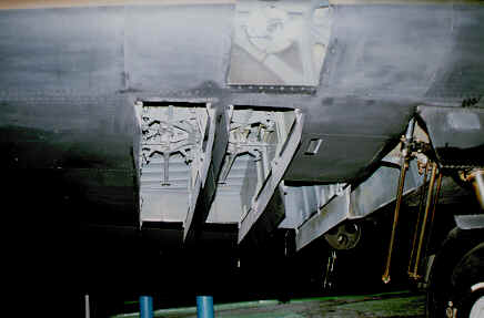
Being used to modern aircraft with their heavy workloads, it is hard to understand that the whole big aircraft was needed to carry a couple of bombs in these tiny bomb bays.
Note also a landing light built into the leading edge of the (starboard) wing.

This is a starboard main undercarriage wheel and leg, seen from the outer side. The two levers extending diagonally to the rear where art of the retraction mechanism and were distinctive for the Battle.

This is a frog’s perspective view of the lower part of the wing’s centre section. The cooler’s rear outlet can be seen in the upper part of the photo, followed by some additional openings. Port wheel well can be seen to the right.
This article was originally published in IPMS Stockholm Magazine in August 1997.