by Michael Scalingi
Building the Saab’s first jet ever
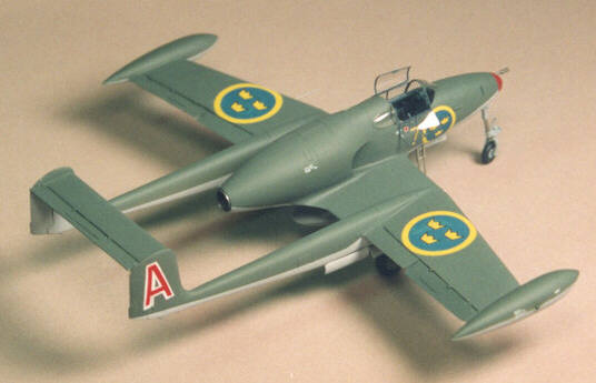
A couple of years ago, a modelling buddy gave me Heller’s 1/72nd model of the Saab J 21A fighter (knowing that I liked Swedish subjects). He said ”see what you can do with that!” Well it sat on my kit shelf for about six months, when seeing it sit there it came to me: ”I know what I can do with that!” The J 21R represents the Big Leap in Flygvapnet history, being the first Swedish jet.
Only two aircraft in history started life as propeller driven, was mass produced, converted to jet power, and was massed produced again. One was the Yak 3, which became the Yak 15, and the other? You guessed it! The Saab J21. While 1/72nd isn’t my primary scale – I like the ”all thumbs” scale of 1/32nd – I though this to be an excellent opportunity to fabricate and use my own conversion parts to make a model not readily available on the open market. I had constructed a ”home brew” vac-form machine, and used it sparingly in a previous project. Now was a chance to really blow (or suck in this case) some plastic!
Mike converted a fairly basic Heller kit ino this little gem. See the text below for details.
Collecting references
First order of business: collect references. No problem! I had in my library the excellent series of books on Swedish Aircraft called Flygplansritningar by Björn Karlström. This series of books all follow the same format: A chronological survey of a particular class of aircraft used by the SAF, each one treated to general arrangement drawings (by the author) in 1/50th and 1/72nd scale along with photographs. For this project I would need Volume 2 Fighters, and Volume 3 Bombers, since the J 21R served in both capacities during it’s career in the late 40’s through the 50’s. Other references I had on hand was Saab Aircraft since 1937 by Hans Andersson, published by Smithsonian Institute Press and an old Profile no. 138 publication on the Saab J21 series.
Planning
So what does it take to convert a J 21A to a J 21R? Well, obviously, it gets a new rear fuselage to house that Goblin turbojet, but wait, there’s more. The tail booms were lowered to align parallel to the line of flight. This combined with a shortening of the main gear struts took away the characteristic tail high sit of the propeller driven version. The fins and rudders were redesigned to accommodate a raised tail plane, to get it out of the way of the jet exhaust. The windscreen became longer and more streamlined, and any scoops and bulges associated with the piston engine were removed. Even the wing went through some modification, the most notable one is that the leading edge air intakes have been deleted.
Vac-forming
Mikes home-built vac from machine with parts for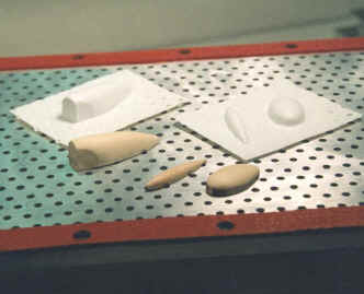 rear fuselage, wingtip tank and gun pod.It is not my intent to go over the details on how to make a vacuum form machine.That would be an entire article in itself. There are a lot of good references on that score: Fine Scale Modeler ran articles on this subject in March/April 1985 and October 1986 issues. Also there’s the fine book by John Alcorn, George Lee, and Peter Cook entitled Scratch Built!, published by Shiffer. This book devotes several chapters to vacuum forming plastic, and is my personal modelling bible. Suffice it to say, any modeller on a shoe string budget, like me, can make an inexpensive Vac-form machine. About the biggest expense is buying the vacuum cleaner! But once you make one, and start using it, just like the J 21R, you have made that Big Leap in modelling, expanding your modelling horizons, and pushing that ”performance envelope”!
Okay, enough pep talk. I chose to vacuum form the major conversion parts (vice trying to carve them from solid stock or something similar) for several reasons:
- I could ensure uniformity of parts, like the tip tanks or the halves of the symmetrical gun pod…
- Some parts, like the rear fuselage, needed to be hollow, to allow for some internal detail, and…
- If I made a mistake, or destroyed a part, replacements can be produced very quickly.
Starting with the fuselage…
The old rear section of the Heller kit was cut off at the panel line just behind the after canopy glazing. I built up the cockpit using the kit seat and some photo etched parts I had in the spares box (actually from the Eduard set for the Hasegawa J 35 Draken kit). The Heller instructions list the cockpit color as black, and I had no other reference to contradict that, so I painted my model’s cockpit black, lighten somewhat with gray so as to lower the intensity. The rear portion that houses the jet engine is perfectly round at its widest point and tapers to a cone at the jet exhaust.
Bass wood master for the rear fuselage part.I carved a mold 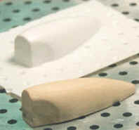 out of bass wood that was one half this shape, spilt horizontally, with the forward portion matching the cross-section of the Heller fuselage. I then vac-formed two of these out of 30 thou plastic card and joined them together. To ensure that the rear would be perfectly round, I covered this part with Milliput, and attached a wood dowel in the hole that would eventually become the jet tail pipe. I chucked this whole affair in a drill press, and slowly turned down the Milliput with a file just like a lathe. I should mention here I like to use Milliput. In fact, outside of super glue, it is the only filler I use. Even thought it’s messy to work with, having to knead it like silly putty, it is a catalyst mixture, so you’re guaranteed that it will be hard, unlike solvent based fillers that never seem to harden completely. Like super glue, Milliput takes to being scribed and thin edges can be made from it.
Once the rear fuselage was smooth, I attached it to the Heller front fuselage. I then cut out the lower portion of the new rear end to accept the Heller wings. I also carved out the holes that would be the intakes for the jet engine. I super glued an aluminium tube in the rear hole and, using more super glue, tapered and smoothed this into the rear fuselage. Into this I inserted another smaller tube to represent The completed 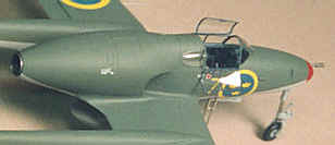 fuselagethe jet pipe. On the inside end of the tube I mounted a small cone, painted flat dark gray to represent the turbine end of the Goblin engine. Up front around the intakes I lined their interiors with sheet plastic. Using Milliput and super glue, I built up the lips of the intakes. At this point, while the wing hadn’t been fitted yet and there was room to work, I ensured to make these intakes as perfect as I could. I also endeavoured to make the wing/fuselage fit as perfect as possible as well, for once they were mated, it would be very hard to blend the two together, never mind fixing imperfections. Once satisfied with the fit of both wing and fuselage, I painted the insides of the intakes black and mounted some photo etched screen for some visual interest. I then set the fuselage aside to work on the…
Wings
The first thing I did to the wings was sand off all the raised surface detail and proceeded to thin the trailing edges to razor thin. I feel it’s very important to do this on all flying surfaces, especially in this scale. For some visual interest, I separated and repositioned the ailerons. The small scoops in the leading edge of the wing for the J 21A were filled with successive layers of super glue, and I added shims to the mating surfaces where the booms attached to the wings to bring them down in line with the centerline of the aircraft. I built up new fins and rudders with sheet stock, as vac-forming these would be a waste of time being so thin. I just tried to match their shape as best I could. I then mounted the booms to the wings, and then the wings to the fuselage. I used the kit’s stabiliser, after thinning the trailing edge and re-positioning the elevator up, something I like to do on all my models, kind of a signature thing. Of course I ensure to position the control stick in the cockpit accordingly!
Detailing the exterior
The main gear was scratch built using plastic tube and metal rod, with wheels from the spares box, with a bit of modification in the wheel hubs. I wanted to simulate the heavy horizontal tread found on a lot of Swedish aircraft of the period, but couldn’t come up with anything convincing. Oh well!
The nose gear was a combination of the kit’s and scratch. I decided the kit’s gear doors looked too clunky, so I used them as molds to vac-form new, thinner ones. I built up the interiors of these with strip stock to simulate formers and reinforcement plates. All the wheel wells and struts were painted the same color as the underside of the model. For the canopy, I took the kit’s windshield and built up layers of super glue to a shape more in keeping with the 21R. Once satisfied with the shape I then proceeded to polish it until no imperfections were found. This bit of ”elbow grease” pays off for I found a polished mold produces clearer parts. This is true whether you’re vac-forming the parts or using the more traditional ”heat and smash” method. I took the other clear parts of the kit, smoothed and polished them, and used them for molds to make new ones as well.
For molding canopies, I use a clear plastic called Vivak, sometimes also called PETG. This stuff forms the clearest of any of the clear plastics I’ve tried – and I think I tried them all between two models!. I use 20 thou for 1/32nd scale models, purchased from Micro-Mark here in the States, and some thinner stock I found locally at a hobby shop (around .008 thick). It is the thinner Vivak I used for this model.
To make canopy frames, I used a trick I picked up from an article in Fine Scale Modeler. Take a piece of clear decal paper and air brush first the interior color of your model, then the exterior color over this. Cut this into thin strips and apply the decal to your canopy to simulate the framing. The interior color will show through on the inside!
I used diluted white glue to attach the clear parts, then spruced up the open parts with small diameter plastic rod and sheet stock to simulate hinges and hand holds. A small application of Future floor polish with a Q-tip helps to make the windows really clear.
Finals
The tip tanks and belly mounted gun pod were fashioned much like the rear fuselage: two halves split horizontally (see the the photo of the vacuum forming machine earlier in this article – Ed.).
Some of the J21Rs where armed with the underbelly gun pack, thus carrying the designation J 21RB. At an IPMS convention I had the opportunity to buy some small diameter stainless steel tubing. This tubing comes in diameters so small that one size is the scale size of 12.7mm gun barrels in 1/72nd scale. I used this for the gun pack in the belly pod, as well as for the wing and nose gun. Larger tubing was used for the cannon muzzle in the nose. This small tubing comes in sizes so as to ”telescope” into one another, so was also perfect for the retractable entry ladder on the right side.
Xtracolor was used throughout this model. For top sides I used X110, Forest Green, and for lower X133 Neutral Gray. I lighten each a little for scale effect, but I think I lighten the gray too much! Flying Colors decals came to the rescue for insignia and yellow numerals, but I was on my own for tail codes.
Red ’A’ on the starboard finFor this I first painted the outer tails white. 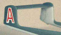 Then I masked over this to make an ”A”. Over this I painted the green and gray, then apply red stripe decals to fill in the letter. I made the sharks mouth on the gun pod in a similar fashion. I first painted the base color, then applied small white triangle decals for the ”teeth”, then blue stripe decals for the ”lips”. Markings are for the 1st Squadron (red) of F7 – Kungl. Skaraborgs Flygflottilj, based out of Såtenäs.
There’s a certain amount of satisfaction from making a conversion of some kit not readily available in production form. That satisfaction is increased markedly when you make the parts for that conversion yourself. I urge all my fellow modellers out there to try a conversion of a kit that requires you to make your own parts, regardless of how small a conversion it is. You will improve your skills, and increase your enjoyment of the hobby at the same time!
This article was originally published in IPMS Stockholm Magazine in September 1998.
