by Martin Waligorski
photos by Martin Waligorski, Mattias Linde and Phillip Treweek
The Improvised Excellence
As is widely known, the Supermarine Spitfire was Britain’s premiere fighter throughout the entire war. Pilots found it to be agile and dependable, it was a fine air-combat plane capable of great speed and superior high-altitude performance. From the engineering point of view, perhaps the most remarkable virtue of the Spitfire was its ability to accept updated engines and armaments and stay competitive as the war progressed.
Early 1942 brought the introduction of the superb German Focke-Wulf 190A on the Channel front, which took the RAF by surprise. In initial engagements, this mysterious Luftwaffe aircraft so thoroughly outclassed the best British mount, the newly introduced Spitfire Mk.V that it created a serious morale problem.
An answer had to be improvised and brought into combat in the shortest possible time. Under the intense pressure from the Ministry of Aircraft Production, Supermarine proposed an interim mark of the Spitfire pending an intended full scale development of the Mk VIII. The result was the Mk IX. The new mark proved vastly superior to the Mk.V in everything except the turn radius. Like a few other British technical improvisations, it lasted a long time, 5665 being built, the second highest number of any Spitfire mark.
The first Spitfire Mk IXs went to No 64 Squadron at Hornchurch in July… the story could continue. The purpose of this essay, however, is to have a look at this famous Spitfire model from the engineering point of view. There’s a lot of enigmatic information about technical configuration of this particular mark. With a very long production run, there had been many small and not-so-small developments introduced on the production line which, although visible, were not reflected in changed type designation. So let’s leave the rest of the type history to other (easily available) sources and have a close look at the aircraft itself!
Supermarine Spitfire Mk. IX in Detail
There are 35 pictures in all, divided by subject into four sections for easier browsing. The main ”hero” of this walkaround session is the Spitfire HF Mk. IXB ser. no. MH 434, G-ASJV owned by the Old Flying Machine Company and currently operated by the Swiss warbird stable of Breitling Fighters. This machine has been photographed during the air display in Uppsala, Sweden in Summer 2001.
The Airframe
A nice view of the HH 434 taxiing. Prominent features of the Mk. IX are immediately apparent – four-bladed propeller, the twin underwing radiators and the more substantial cowling housing the Merlin 60-series engine.
Photo: Mattias Linde
Same aircraft parked on tarmac prior to air display.
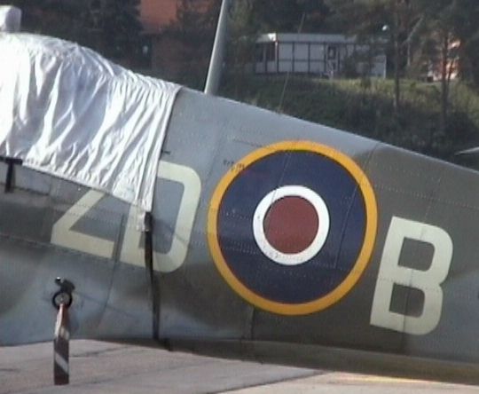
The original RAF camouflage of Dark Green and Ocean Gray over Medium Sea Grey has been faithfully restored on this aircraft, with exception of the yellow spinner which is a recognition mark of Breitling Fighters, the warbirds team operating the aircraft. Photo: Martin Waligorski
Another view of the same aircraft. Photo: Martin Waligorski
View of the wing upper surface. As on earlier (and later) Spitfire versions, it is striking how thin the Spitfire wing actually was. Upon closer inspection it can be seen that the ailerons of this version were metal-covered.
Photo: Martin Waligorski
The area immediately in front of the cockpit was occupied by the main fuel tank. The tank was protected with an external armor plate, resulting in a visibly raised panel. Photo: Martin Waligorski
The rear section of the fuselage. It is notable that the panels were not flush-rivetted as on, for example, Messerschmitt Bf 109. Although obviously the simpler technology, it never seemed to hamper the Spitfire’s excellent performance.
Photo: Martin Waligorski
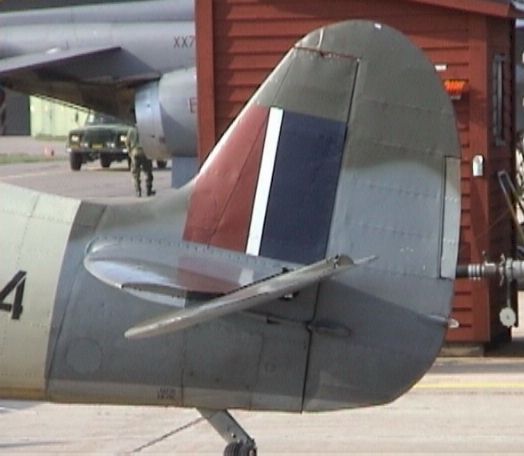
The vertical tail of the Spitfire remained virtually identical through all production marks from Mk. I to Mk. IX. However, later Mk. IX machines were upgraded with an extended fin tip initially designed for the Griffon-powered Mk. XII.
Photo: Martin Waligorski
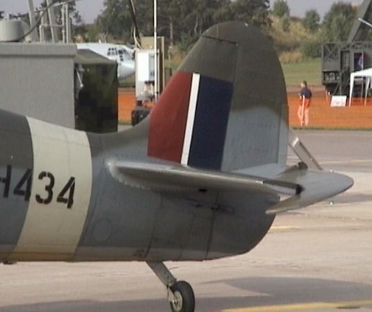
Early during the Mk. IX production, the elevator shape was also changed. The improved elevator featured the larger horn balance with ”kinked” cutout line visible here. Note how the tail wheel swivels around itself with the leg remaining inline with the fuselage. Photo: Martin Waligorski
Close-up of the elevator horn balance and trim tab actuator on its upper surface. Photo: Martin Waligorski
Fine detailed view of the fabric covering on the fin, the actuating rods and tail light. Photo: Martin Waligorski
The Powerplant
Close-up of the nose housing the Merlin 60-series engine. The double-stage supercharger placed behind the engine necessitated a much longer nose as compared to the earlier single-stage versions such as the Mk. V.
Photo: Martin Waligorski
Many modellers and historians alike refer to the top the Mk. IX cowling not only being longer but featuring a raised hump on its upper side. This photo shows the very feature, but as can be seen, it is not very prominent, indeed from some angles it disappears almost entirely (compare with the previous photograph).
The origin of the hump is as follows. When the new Merlin 60 engine was mated to Spitfire Mk. V airframe, it was not only longer, but its thrust line had to be angled down a little. With the propeller axle retained at the same level as before, the rear part of the top engine block had to be tilted up and came up higher than in the Mk. V. This in turn required more space under the rear top cowling, just in line and behind the last exhaust stack.
Actually, the author of these words believes that there were at least two different shapes of the production Merlin 60 cowling, perhaps a result of manufacturing differences between Supermarine and Castle Bromwich factories, the two major producers of the type. Photo: Martin Waligorski
The enlarged carburettor intake with built-in compact Vokes Aero-Vee universal dust filter was another feature introduced on the Mk. IX. It became standard only later during Mk. IX production, but was also retrofitted to many earlier machines.
As the picture shows, the intake was equipped with a closing shutter which prevented dust ingestion when taxiiing in dusty field conditions. It often remained closed on even on parked aircraft. Photo: Martin Waligorski
Front view of the port underwing radiator. The Mk. IX radiators had enlarged frontal area as compared to the earlier Spitfire marks. Both radiators were identical rather than being mirror images of each other, divided into two sections – the starboard being an oil cooler, port side being occupied by the intercooler. Photo: Martin Waligorski
Close-up of the four-bladed Rotol propeller. Photo: Martin Waligorski
Profile view of the propeller spinner. Photo: Martin Waligorski
 View of the propeller blade. The decal is a modern one of Breitling Fighters and does not come from the original manufacturer. Photo: Martin Waligorski
The division of upper cowling panel barely visible in line with the first exhaust pipe indicates that this aircraft has been originally produced at the Castle Bromwich Aircraft Factory. The Supermarine-produced machines had a one-piece upper cowling cover. Photo: Martin Waligorski
The Mk. IX and later Merlin-powered Spitfire versions standardised on six individual exhaust stacks shown here, but their presence alone cannot be used as a definitive recognition feature of the Mk. IX. Some late-production Mk. V also had six exhausts. This view also shows the shape of Dzus cowling fasteners. Photo: Martin Waligorski
Wing & Undercarriage details
The wing root fillet with solid leading edge visible here was not common for all Mk. IXs. Early production batches powered by Merlin 61 and 63 series engines had a relatively large circular air intake there serving the fuel cooler, a device used to prevent the fuel from boiling at the relatively high climbing speeds of the new fighter. The fuel cooler installation was identical as on the previous Mk. VII high-altitude version. It is not a widely-known feature as it was later removed and none of the surviving Mk. IXs seems to have it retained.
In the same spot, earlier Spitfire marks had a smaller opening for a gun camera. Because of the fuel cooler installation, it was initially omitted altogether on Mk. IXs, and later on moved to the starboard wing fillet. Photo: Martin Waligorski
Close-up on the rear part of the wing fillet. Note the different style of riveting compared to that on the fuselage.
Photo: Martin Waligorski
The streamlined fairing of the wing-mounted Hispano cannon.
In the initial production, all Mk. IXs were equipped with the ”C”-type wing. This wing could carry both cannon and machine gun armament, and is often associated with four protruding cannon barrels often seen on the Mk. VC. However, because of the weight restrictions caused by the use of the more powerful – and heavier – engine, the Mk. IX could not carry the full complement of four cannon, and all production machines were equipped with two cannon (located in the inboard bays) and four machine guns.
The abandonment of four-cannon option on the Mk. IX had two consequences. First, the ”leftover” wing cannon mount resulted in the short stub outboard of the cannon barrel, plugged with a solid rounded tip. Later on, as it has been realized that the the second cannon bay will never be used, the stub was removed altogether, as seen on this photograph.
The second consequence was the shape of the upper wing blisters. These blisters were introduced to provide sufficient room for the ammunition drums of the Hispano cannon. Initially the ”C” wing used a single wide blister covering the twin cannon bay. As it was realized that only one cannon was necessary, a new blister was introduced to the Mk. IX production line. This blister was narrow and elongated, and can be seen on the wing photograph in The Airframe section of this essay.
Still later, the wing was modified to the ”E” type. Structurally, this was identical to the ”C” wing, but adopted to carry two 0,50″ machine guns in place of the four 0.303″ Brownings. Photo: Martin Waligorski
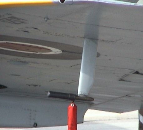
The Pitot tube was mounted under the port wing tip. Photo: Martin Waligorski
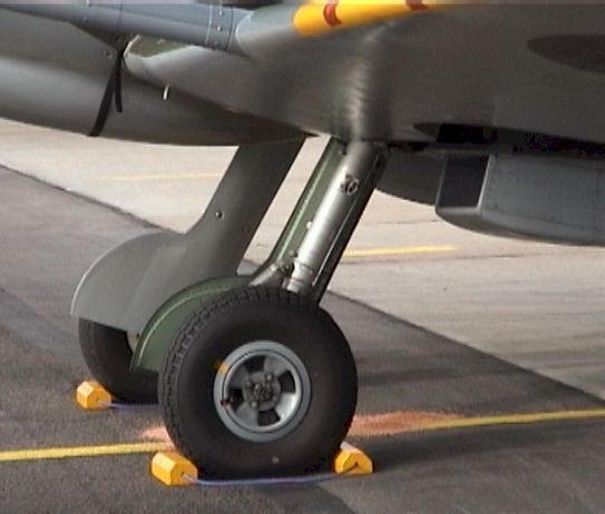
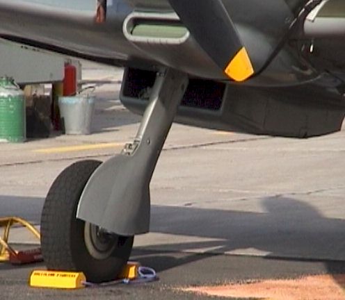
The initial production Mk. IX had the same undercarriage as the Mk. V and earlier marks. This early type is recognizable by five-spoke wheels and perfectly flat undercarriage covers.
The above photograph shows the mid-production type of undercarriage, which was an entirely new construction. The main legs were not only strengthened, but also raked forward at a steeper angle to counter the increased nose weight. The new four-spoked wheel featured a larger tyre.
Towards the end of the war, production shifted to three-spoke wheel which can bee seen on many late marks of the Spitfire. Photo: Martin Waligorski
Another new detail of the updated undercarriage leg was a forward-facing scissor link over its oleo part – barely visible here behind the wheel cover. Also the covers differed from the earlier marks, having a distinctly bulged appearance, necessary as the thicker tyre could no longer fit into the thin wing when retracted. Photo: Martin Waligorski
A peek into the starboard wheel well, showing the compact undercarriage retraction mechanism.
Photo: Phillip Treweek
Cockpit
Most Spitfire Mk. IX were fitted with the same type of canopy, a Malcolm Hood with bulged sides, as shown in this view. Only the few earliest examples were equipped with a flat-sided model known from the Mk. V. Another change introduced during the production run was a round rear-view mirror replacing the earlier rectangular type.
Note that the supporting bar connecting the top of the armored plate with the fuselage spine is located on the inside of the plexiglass. Photo: Phillip Treweek
The canopy featured an integrated bullet-proof windscreen. The windscreen part was mated to the cockpit cutout with an additional bit of metal skin which is clearly visible from this angle. Photo: Phillip Treweek
Close-up on the pilot headrest mounted to the protective armour plate. Photo: Phillip Treweek
Details of the cockpit entry door with the prominent escape crowbar fitted to its inner surface.
Photo: Phillip Treweek
Look into the cockpit, almost in original condition except for the modern seat cushion and some radio wiring stuck beside it. Note that there is no solid cockpit floor, but only two moving circular bars connected to the rudder pedals in the front. Photo: Phillip Treweek
Another view showing the spade grip-style stick so typical for the British fighters of the era. The button on top of the grip is the compound gun trigger, serving both the cannon and machine gun armament.
Mounted to the horizontal fuselage frame on the cockpit sidewall is the throttle control (the item with the red handle). The colors of this cockpit are matching the original factory finish, with Interior Green sides and black instrument panel and other equipment. Photo: Phillip Treweek
Instrument panel in original condition. The round item on the bottom side of the photo is the undercarriage control unit. Photo: Phillip Treweek
View of the sizeable reflector gunsight. The headphones are of modern variety. Photo: Phillip Treweek
This article was originally published in IPMS Stockholm Magazine in December 2001.


