by Ricardo Dacoba
English translation by Martin Waligorski
With the big Heinkel He 177, Revell has once again delighted us with an excellent kit. This one fills also an important void – the only previously available kit of this aircraft was released in Airfix Series 5. It was good for its time but more recently has been in dire need of retirement.
The Revell kit comprises 6 sprues moulded in pale grey plastic with a total of 215 pieces. My sample was notably free of flash or sink marks. The level of detail is very good, particularly in the cabin area – a wise choice by Revell since the large transparencies allow quite much of the interior to be seen.
Panel lines and surface detail have been rendered in recess, a bit overstated for my taste but in par with other Revell kits of recent years, meaning that they were acceptable.
The enclosed decal sheet contained markings for two aircraft:
- He-177 A-5 (6N+HM) of 4/KG 100 in Chateaudun, France, 1944.
- He-177 A-5 (F8+CK) of 2/KG 40 in Bordeaux- Merignac, France, late 1944.
The decal sheet was comprehensive, but the decals are notably thick. The latter could be at least partially remedied by gently sanding the sheet with 1200-grit sandpaper.
Beginning the project
Prior to commencing work on the model I collected as much information, drawings and photos of He 177 as I could. This was important since my objective was to make several modifications to the kit such as opening of the flaps, detailing the undercarriage, engine compartments etc.
With the information assembled, I went about planning the sequence of work, another important preparation to avoid unnecessary misfortunes during construction.
Wings
I started with separating the landing flaps from the wings. The thereby exposed interior of the wing was detailed with internal rib and longeron structure made from strips of plasticard – a simple but a bit boring task. To speed up work, the ribs were all cut from 1 mm plasticard with some excess and glued in place. Then the entire assembly was sanded down to uniform profile using an improvised sanding block.
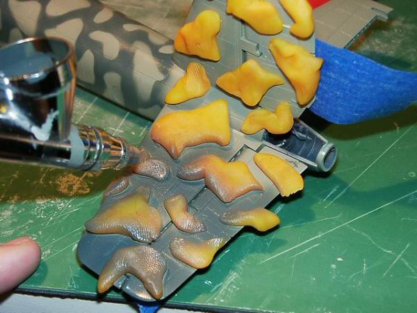
The flaps on the He 177 were of Fowler type and therefore new parts had to be made. I created them from strips of epoxy putty. Slots and supports were provided for hinging mechanism, matching the hinge locations on the fixed part of the wing.
Deployed flaps with interior detail
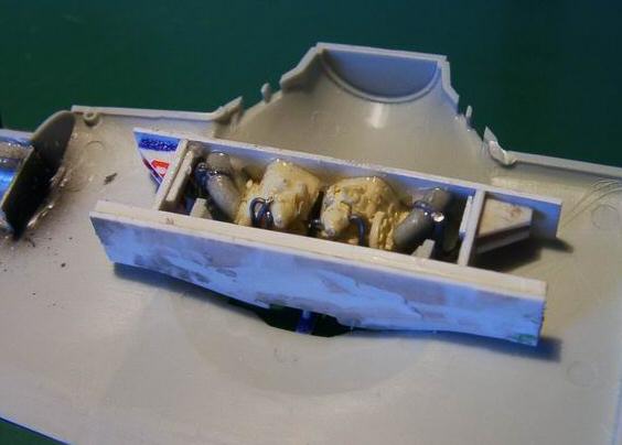
Wheel Wells
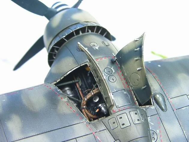
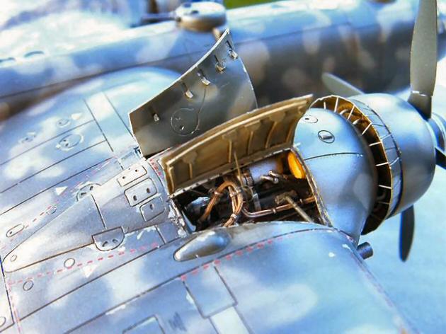
The kit’s undercarriage was very well detailed. In contrast, wheel wells remained enclosed on the ground, and were therefore moulded by Revell in a rather simplified fashion. This, however, wasn’t enough for me, since rear accessories of the engines would be visible through the opening in the nacelles – the He 177 had no firewalls!
In order to correct this problem I first removed the integrally-moulded wells using a motor tool and 5mm grinding bit. Since I intended to reveal the engine in the right nacelle, the appropriate access panels were cut out and all visible edges sanded carefully down to scale thickness, first roughly with the motor tool and then scraped with No. 11 blade.
The new wheel well was built as a box of 1mm plasticard. Its interior was detailed with new undercarriage supports, hydraulic plumbing, wiring and some electrical boxes made from plastic. I then made a rubber mould of the entire assembly and simply produced a resin copy for another wing. Thus I saved time and achieved better precision.
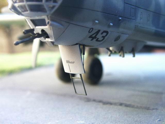
Tail Wheel
Mounting the piece No. 54 which is the tail wheel housing left an open gap to the fuselage, which is incorrect. This was duly blanked off with a piece of plasticard. I installed the tail wheel, previously painted in greenish-grey RLM 22.
The covers of the tail undercarriage were a little heavy in the kit, which I the reason why I replaced them by scratchbuilt ones made of aluminium plate and plasticard. I also added the new actuators to the covers.
Daimler-Benz DB 606 Engine
The notorious DB 606 engine was actually a pair of DB 603s coupled with a common gearbox.
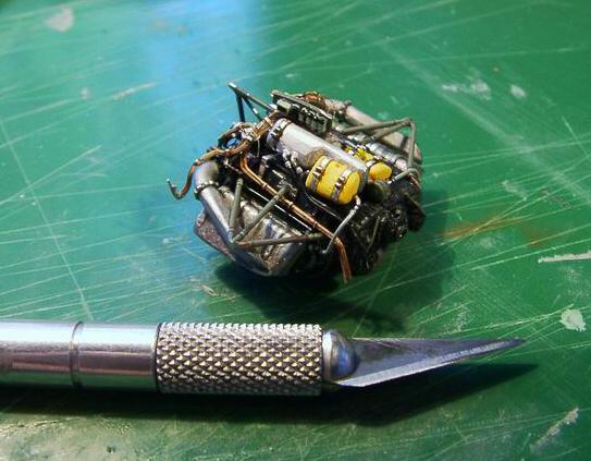
I scratchbuilt a complete right engine, and (as mentioned before) part of the left engine visible through the undercarriage bay.
Scratchbuilding a complete engine was something of a project in itself, especially as there were no readily available aftermarket parts. I resorted to a Bf 109 resin engine from Aires and cast it in three additional resin copies. Two of the engines had their rear segments sawn off and utilized in the left wheel well. Another two formed the basis of the complete engine.
In order to build the complete DB 606, I had to change the position of one of the superchargers to the opposite side of the engine block, produced a new common gearbox, scratchbuilt the supporting frame from copper wire, formed exhaust manifolds from epoxy putty, shaped oil tanks from leftover bits of resin and finally added a few other accessories including the prominent wiring. Phew!
The assembled engine was mated to the wing nacelle to reveal and rectify any fit and alignment problems. Once they have been resolved to my satisfaction the engine was completely painted and weathered prior to installation in the starboard nacelle.
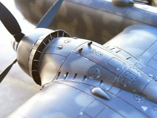
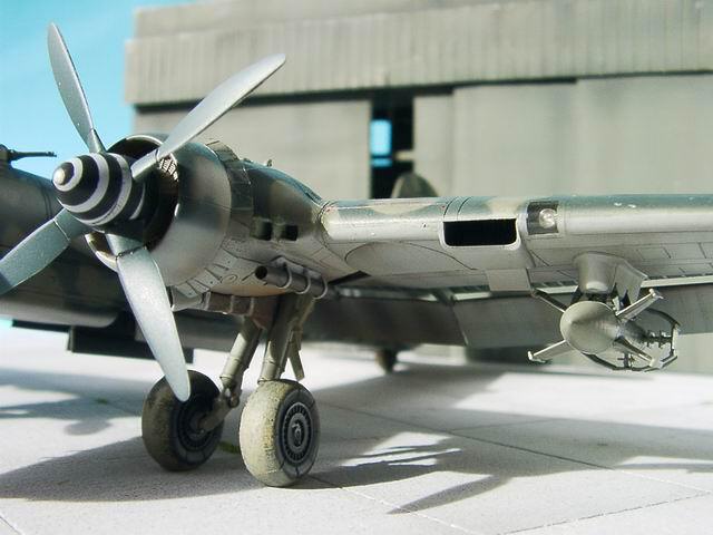
Main Radiators
In order to further improve the appearance of the engines I opened the cooling flaps of the circular radiators, adding their actuating rods and simulating some interior detail beneath such as water plumbing and the radiators themselves.
The new collar of cooling flaps was turned on my Unimat lathe. The individual petals were then added to its outer surface to produce raised detail, and some additional detail scribed on. In my usual fashion, this part was then used as a master for a rubber mould and two very thin resin copies.
The cowlings were then modified to accept the new collars, and the new parts attached with superglue. With these and all the and new interior detail inside the cowlings, I had to work out the way of attaching radiators to the engines, particularly to my completed right engine. Scale-thickness supports were produced based on the references, and water plumbing connected with the engine.
Detailing of the baffle plates and cooler/engine cowlings
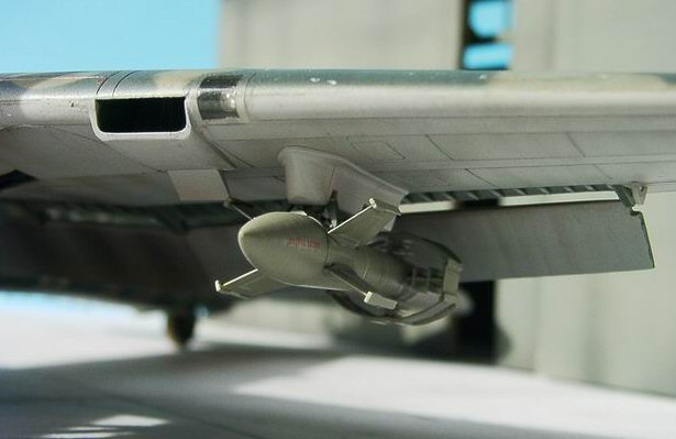
Secondary Radiators
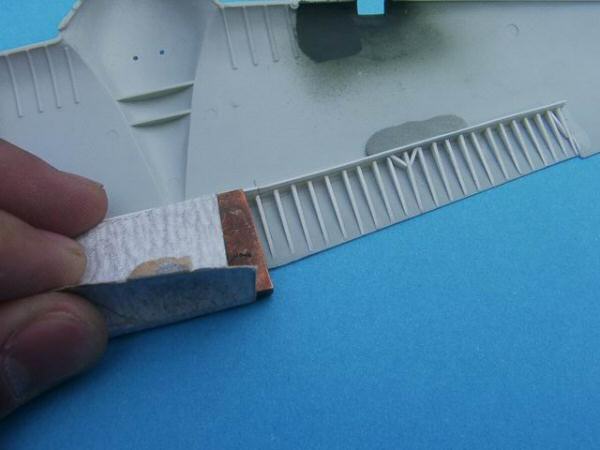
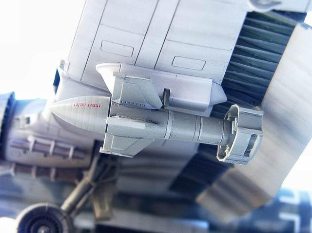
I thought that the kit’s underwing oil radiators were very basic – or perhaps the appetite grows with eating… Anyway, I decided to improve them, too. I scratchbuilt radiators of greater thickness, with detail of both sides. The adjustable exhaust control flap was replaced with a new thinner one formed from thin aluminium plate.
I also decided to open up the top access hatch of one of the wing radiators. Additional detailing in this area included oil plumbing and electric wiring for de-icing installation incorporated in the wing’s leading edge.
With this step completed, I could finally close the wing halves and set them aside, turning my attention to the fuselage.
Cabin Interior
The crew compartment was finished practically as per kit instructions. I only added a few electrical cables for the main instrument panel and seat belts. Oh, and also a ”trunk” for spent cartridges of the front machine gun. Everything else in the cabin looked good enough to me.
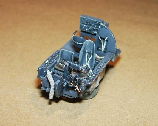
I have airbrushed all the interior in RLM 66, picking up the recessed detail certain with a wash of black colour, followed by brush-painting of selected details in appropriate colours.
Tail Unit
The movable surfaces of the tail were cut off and repositioned at an angle to give a model a more lifelike appearance. The cutting could not be done in a straight line, so I used my ”normal” procedure of thinning down the stabiliser halves from the inside to a degree that a single cut with No.11 blade was all that was needed to cleanly separate the elevators.
With the separated movable surfaces the stabiliser halves were joined together and the resulting rear gap filled with epoxy putty, then sanded to finish.
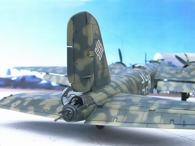
The control surface actuators were destroyed in the cutting process which was just as well because they were quite overscale. The replacements were made from aluminium wire.
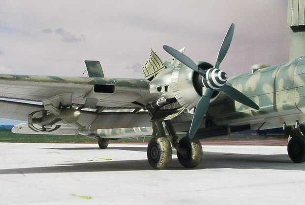
Propellers
A detail too often ignored but easily noticeable in 1/72 scale is the excessive thickness of the propeller blades. The propellers included in Revell’s He 177 were no exception. I opted to produce new blades from aluminium. This material was chosen not only because of its relative rigidity, but also because it lends itself well for reproducing realistic signs of wear.
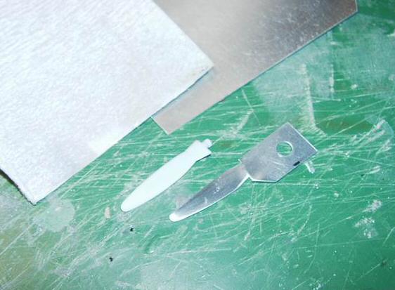
Refining propeller blades
The new blades started as 1mm aluminium plate which was cut into rectangles roughly 1×4 cm in size. Later a blade contour was traced onto each piece, and the excess cut off and gradually filed away until the required outline and profile was achieved. Once I had the well formed blades I gently twisted them to the definitive form.
The new blades were installed in the kit’s propeller hub. When building a Heinkel He 177 it is important to keep in mind that the propellers rotated in opposite directions. Consequently, the right and left propeller were mirror images of each other.
Fuselage
Before closing the fuselage I took the opportunity to improve the dorsal gun turret. The machine gun barrels were replaced with detailed resin items ”borrowed” from a set for a Bf 109.
Dry-fitting the wings to the fuselage revealed that the total span of the model was 2 mm short of what it should be. To rectify this, I produced a spacer from 1 mm plasticard in each wing root, which solved the problem perfectly.
Minor Details
Among the smaller details I added new flame dampeners to the exhausts; those provided with the kit were not accurate in form nor length. The replacement parts were pieces of Evergreen plastic tubing with holding straps made from tin foil.
The ventral antenna was replaced with new one made of copper wire.
Another significant step that followed prior to painting was tracing the rivet lines. Using the references, rivets were traced on the surface of the model using a homemade tool with a small gear of an old watch.
Antenna wires (actually added when the model was already painted) were reproduced with fine black nylon thread and attached with superglue.
Painting
After all the work done to the model, I found it essential to wash it thoroughly with a little isopropyl alcohol to remove any grease from the surface and ensure good paint adhesion.
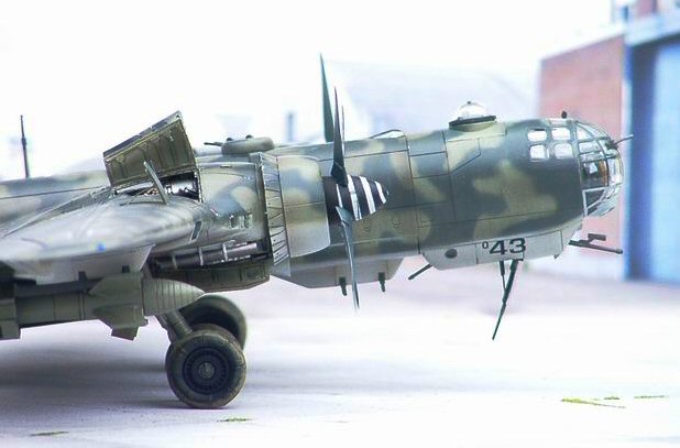
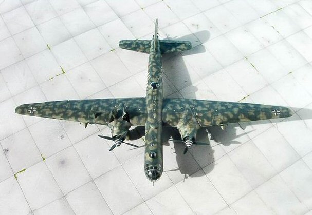
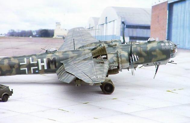
The machine I chose to represent was 6N+HM from 4/KG 100 in Chateaudun, France. The Camouflage of this machine consisted of three colours, RLM 65 for the lower surfaces and an irregular pattern of RLM 02 and RLM 73 for the upper surfaces. The paints that I used were Xtracolor enamels applied with airbrush. I started with the RLM65 as the lightest colour, allowing it to dry for 24 hours.
The upper surfaces were masked and painted in a reversed order compared with the original – first the splotch colour and then the darker background. First, all the upper surfaces of the model were given a coat of RLM 02 and allowed to dry thoroughly. To mask the splotches, I used blobs of office clay shaped in different forms. I worked in zones in order to avoid leaving the clay attached to the model for very long – there was always a risk that the clay might leave some residue on the surface.
Once all the splotches had been painted, I reviewed and retouched the paintwork using my airbrush free-handed and at the finest setting.
With the basic paint work complete, I applied the decals, carefully trimming off the excess carrier film.
The larger markings – crosses and letters on the fuselage were actually painted-on using self-adhesive vinyl masks.
The weathering was carried out with the airbrush, using Tamiya’s X-19 Smoke. To emphasize recessed detail, a wash of black and brown watercolour was applied. I let it partially dry and then wiped off the excess with a damp cloth, leaving some subtle streaking and shading on the surfaces.
I finally applied a layer of fine satin acrylic varnish from Testors.
I’m pleased with my Heinkel. I have picked a great kit and managed to take it a step or two further. I hope you’ll like the result as much as I do.
Ricardo Dacoba 2006
this article was originally published in IPMS stockholm Magazine in March 2006